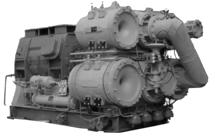
Designed to compress atmospheric air used in various industries in pneumatic equipment, pneumatic tools and technological processes.
COMPRESSOR 32VC-100/9

32ВЦ-100/9
Cleaning the flow path and connector surfaces
The rotor can be repaired in the following scope:
1. Cleaning the rotor from deposits
2. Flaw detection of the rotor by VIC, PVC, MPD methods
3. Replacement of defective parts: sealing ridges; gear bushings; thrust disc; axial relay disk; impeller; shaft
4. Grinding necks, thrust disc
5. Replacement of bearings, filing on breadcrumbs and alignment of babbitt filling. With rotor positioning in the flow path along the housing bores
During long-term operation of the compressor, misalignment of the embedded parts of the compressor may occur (due to warpage of the housing, wear of the centering pins, etc.). Misalignment leads to unevenness of the gap between the rotor and the embedded parts, it is not uncommon for them to touch. This defect leads to a decrease in compressor performance.
Replacement of gas (air) seals is carried out in order to ensure the drawing values of the clearances in the seals to bring the compressor capacity to the formulated values.
Replacement of oil seals is carried out in order to maintain the drawing values of the clearances in the seals to prevent oil leaks.
1. Cleaning the connector surfaces
2. Replacement of bearings, filing on the outer diameter, sizing of the babbitt layer, with setting the center distance, skew and intersection of the axes of the gear pair
3. Grinding of necks, thrust disc of the gear pair
4. Balancing the gear pair
1. Replacing bearings
2. Replacing the oil seals
3. Aligning the rotor in the stator magnetic field
4. Balancing the rotor of the electric motor
Compressor unit alignment, reducer-compressor, reducer-electric motor
1. Mechanical cleaning of the tube bundle
2. Chemical cleaning of the tube bundle
3. Pressure testing of the heat exchanger
| Productivity | m³ / s (m³ / min) | 1,67 (100) |
| Initial pressure | MPa (kgf / cm²) | 0,098 (1) |
| Final pressure | MPa (kgf / cm²) | 0,88 (9) |
| Rotor speed | rpm | 25086 / 25262 |
| Electric motor | °С | С 4ARM-630 / 1000 UHL 4 / STD-630-2RUHL4 |
| Power | kW | 630 |
| Overall dimensions of the installation | mm | 3600х1800х1800 |
| Weight | kg | 10200 |
The compressor is a monoblock compact unit with an overdrive gear and gas coolers built into the compressor housing.
Compressor casing, electric motor, lubrication unit, oil and water supply systems are mounted on a common frame, which are at the same time an oil tank.
Compressors are assembled from two modules, each of which consists of a rotor resting on two journal bearings, with two impellers mounted on it cantilevered and parts forming the flow path of the stages (blade diffusers, volutes, suction chambers, gas coolers, moisture separators).
The module housings are cast iron, with an internal air passage from stage to stage within the module, and from module to module - with an external bypass. The rotors are made of high alloy steel. The impellers are fitted back-to-back, which balances the axial forces from gas-dynamic overloads.
Lubrication system - circulating, forced with free drainage of oil into the tank. Lubricating oil - TP-22s.
