The centrifugal compressor K1500-62-2 is designed to compress and supply primary air to oxygen separation units.
COMPRESSOR K-1500
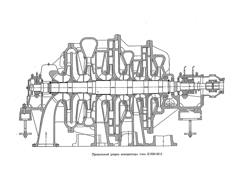
К1500-62-2
Manufacturer: CJSC "Nevskie Zavod"
Centrifugal compressor fault detection
Centrifugal compressor repair
Cleaning the flow path and connector surfaces
The rotor can be repaired in the following scope:
1. Cleaning the rotor from deposits
2. Flaw detection of the rotor by VIC, PVC, MPD methods
3. Replacement of defective parts: sealing ridges; gear bushings; thrust disc; axial relay disk; impeller; shaft
4. Grinding necks, thrust disc
5. Replacement of bearings, filing on breadcrumbs and alignment of babbitt filling. With rotor positioning in the flow path along the housing bores
Compressor rotor balancing
Re-centering of diffusers, diaphragms
During long-term operation of the compressor, misalignment of the embedded parts of the compressor may occur (due to warpage of the housing, wear of the centering pins, etc.). Misalignment leads to unevenness of the gap between the rotor and the embedded parts, it is not uncommon for them to touch. This defect leads to a decrease in compressor performance.
Replacing gas (air) seals
Replacement of gas (air) seals is carried out in order to ensure the drawing values of the clearances in the seals to bring the compressor capacity to the formulated values.
Replacing oil seals
Replacement of oil seals is carried out in order to maintain the drawing values of the clearances in the seals to prevent oil leaks.
Gearbox repair
1. Cleaning the connector surfaces
2. Replacement of bearings, filing on the outer diameter, sizing of the babbitt layer, with setting the center distance, skew and intersection of the axes of the gear pair
3. Grinding of necks, thrust disc of the gear pair
4. Balancing the gear pair
Electric motor repair
1. Replacing bearings
2. Replacing the oil seals
3. Aligning the rotor in the stator magnetic field
4. Balancing the rotor of the electric motor
Compressor package alignment
Compressor unit alignment, reducer-compressor, reducer-electric motor
Repair of heat exchange equipment
1. Mechanical cleaning of the tube bundle
2. Chemical cleaning of the tube bundle
3. Pressure testing of the heat exchanger
| Volumetric capacity at initial parameters (air pressure 0.096 MPa, air temperature 20 ° C, relative humidity 50%), | m / min | 1590 |
| Productivity at 20 ° C and 0.101 MPa | m / min | 1480 |
| Final pressure | MPa | 0,736 |
| Power consumption (at the motor coupling) | kW | 7400 |
| Compressor rotor speed | rpm | 4470 |
Brief description of the design. The compressor consists of a single-cylinder compressor itself, an electric drive motor, a step-up gearbox and systems: oil, regulation, control, monitoring, protection and signaling.
Compressor - six-stage, three-section.
The air is cooled in intermediate air coolers installed after the first and second sections. The air coolers are located in the basement. A terminal air cooler is designed to cool the air after the compressor.
Reducer - single-stage, horizontal, with double-sided helical gearing, installed between the electric motor and the compressor.
The compressor is driven by a synchronous electric motor of the STD-10000-2U4 type, with a power of 10,000 kW, a voltage of 6,000 or 10,000 V, and a rotation frequency of 3,000 rpm.
The compressor rotor with the gear wheel and the gear wheel with the electric motor rotor are connected by gear couplings.
Oil system - forced, circulating, provides oil supply for lubrication of the unit and control and protection units.
The unit's operating modes are controlled by a throttle valve installed in the suction line of the compressor.
The control, management and protection system includes:
a heat control panel, on which instruments for remote measurement of the unit's operating parameters, emergency and warning signaling are concentrated;
local panel with equipment for starting and stopping the compressor;
devices for protection against surging, backflow of air, axial displacement of the rotor, impermissible pressure drop in the bearing lubrication system, impermissible temperature rise of the liners.
The scope of delivery of the compressor includes: the compressor itself, the gearbox, couplings between the electric motor and the gearbox, as well as between the gearbox and the compressor, the oil system, air coolers, control and protection devices, the electric motor.
Production started in 1963.