The centrifugal compressor K400-51-2 is designed for compression and supply of contact gas for dehydrogenation of isopentane and isoamylenes in the production of synthetic rubber.
COMPRESSOR K400-51-2
К400-51-2
Manufacturer: CJSC "Nevskie Zavod"
Centrifugal compressor fault detection
Centrifugal compressor repair
Cleaning the flow path and connector surfaces
The rotor can be repaired in the following scope:
1. Cleaning the rotor from deposits
2. Flaw detection of the rotor by VIC, PVC, MPD methods
3. Replacement of defective parts: sealing ridges; gear bushings; thrust disc; axial relay disk; impeller; shaft
4. Grinding necks, thrust disc
5. Replacement of bearings, filing on breadcrumbs and alignment of babbitt filling. With rotor positioning in the flow path along the housing bores
Compressor rotor balancing
Re-centering of diffusers, diaphragms
During long-term operation of the compressor, misalignment of the embedded parts of the compressor may occur (due to warpage of the housing, wear of the centering pins, etc.). Misalignment leads to unevenness of the gap between the rotor and the embedded parts, it is not uncommon for them to touch. This defect leads to a decrease in compressor performance.
Replacing gas (air) seals
Replacement of gas (air) seals is carried out in order to ensure the drawing values of the clearances in the seals to bring the compressor capacity to the formulated values.
Replacing oil seals
Replacement of oil seals is carried out in order to maintain the drawing values of the clearances in the seals to prevent oil leaks.
Gearbox repair
1. Cleaning the connector surfaces
2. Replacement of bearings, filing on the outer diameter, sizing of the babbitt layer, with setting the center distance, skew and intersection of the axes of the gear pair
3. Grinding of necks, thrust disc of the gear pair
4. Balancing the gear pair
Electric motor repair
1. Replacing bearings
2. Replacing the oil seals
3. Aligning the rotor in the stator magnetic field
4. Balancing the rotor of the electric motor
Compressor package alignment
Compressor unit alignment, reducer-compressor, reducer-electric motor
Repair of heat exchange equipment
1. Mechanical cleaning of the tube bundle
2. Chemical cleaning of the tube bundle
3. Pressure testing of the heat exchanger
| Volumetric capacity at initial parameters | m3 / min | 400 |
| Performance at 20 ° C and 760 mm Hg st | m3 / min | 328 |
| Final gas pressure at the outlet of the compressor discharge pipe | kgf / cm2 | абс. 5,0 |
| Initial gas pressure at the entrance to the suction inlet of the compressor | kgf / cm2 | абс.1,02 |
| Initial gas temperature at the entrance to the compressor suction pipe | °С | 45 |
| Density of dry gas at 20 ° C and 760 mm Hg. st | kg / m3 | 1,835 |
| Relative humidity of gas at the entrance to the compressor suction pipe | % | 100 |
| Power consumption (at the motor coupling) | kW | 1500 |
The compressor unit consists of a single-cylinder compressor, a step-up gear, an electric drive motor and systems: oil, control, protection, control and signaling.
The compressor and all accessories are explosion-proof, allowing their operation in an explosive room of class B-1a with the category and group of explosive mixture ZT4.
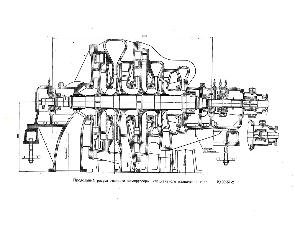
The compressor is a single-cylinder, five-stage (fig. 50). The gas between the sections is cooled in intermediate gas coolers. Gas coolers - welded with smooth tube bundles, located directly under the compressor. Separators installed after each gas cooler separate the moisture released from the gas in the gas coolers.
The tightness of the compressor is ensured by end-type oil seals.
The compressor is driven by an asynchronous electric motor of type 2АЗМП-2000/6000-U4, power 2000 kW, voltage 6 kV, rotation frequency 2975 rpm. ... The electric motor is explosion-proof, blown under excess pressure in a closed cycle.
The gearbox with the compressor rotor and the electric motor is connected by gear couplings.
The unit is supplied with oil by an oil system that supplies oil for lubrication of the bearings of the electric motor, compressor, gearbox of mechanical seals, gear drive of the gearbox and gear couplings.
Control, protection, control and signaling systems include:
a panel on which devices are concentrated for remote control of start-up and shutdown operations of the unit, measurement of operational parameters of the unit, emergency and prudent alarms;
performance sensors;
protection devices against the backflow of gas from the network to the compressor, surge, axial displacement of the compressor rotor, lowering the oil pressure in the lubrication system of the unit bearings, increasing the temperature of the unit bearing shells.